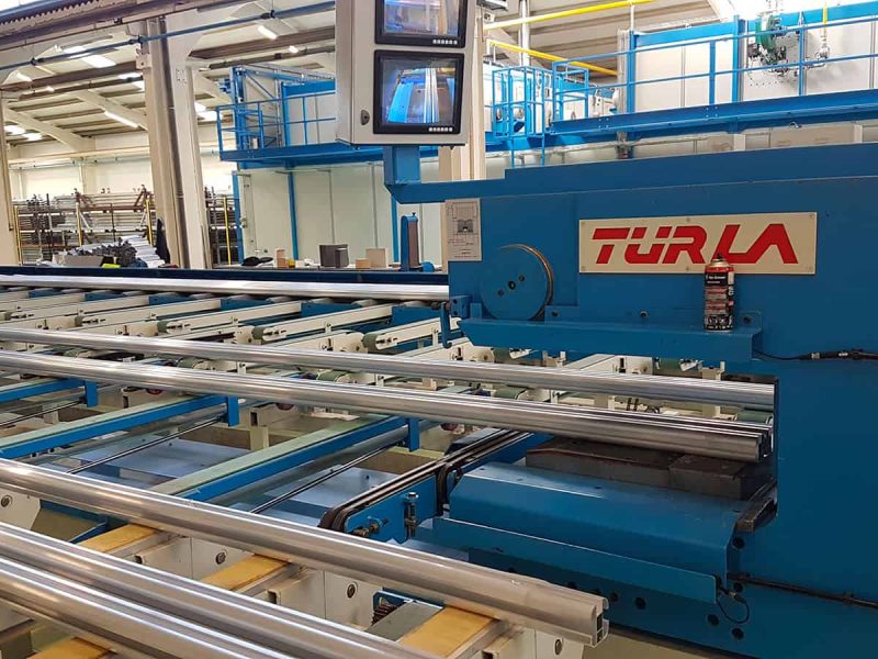
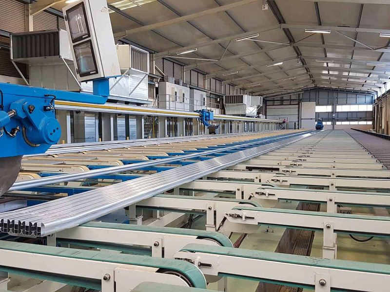
Cooling table
Cooling table
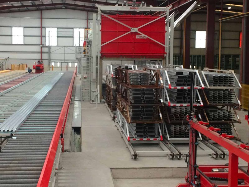
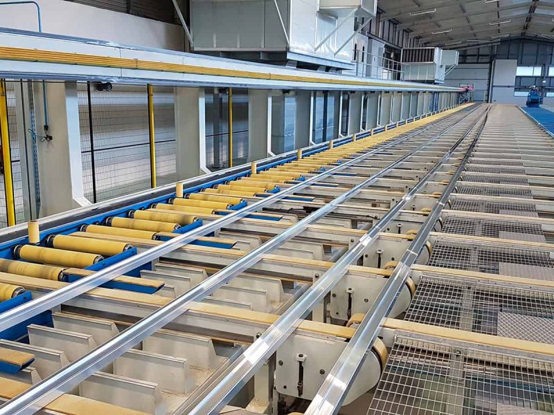
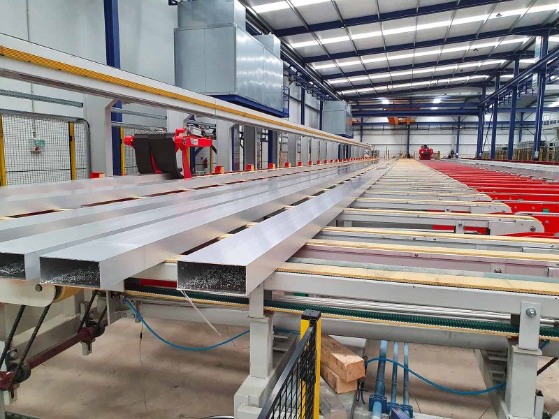
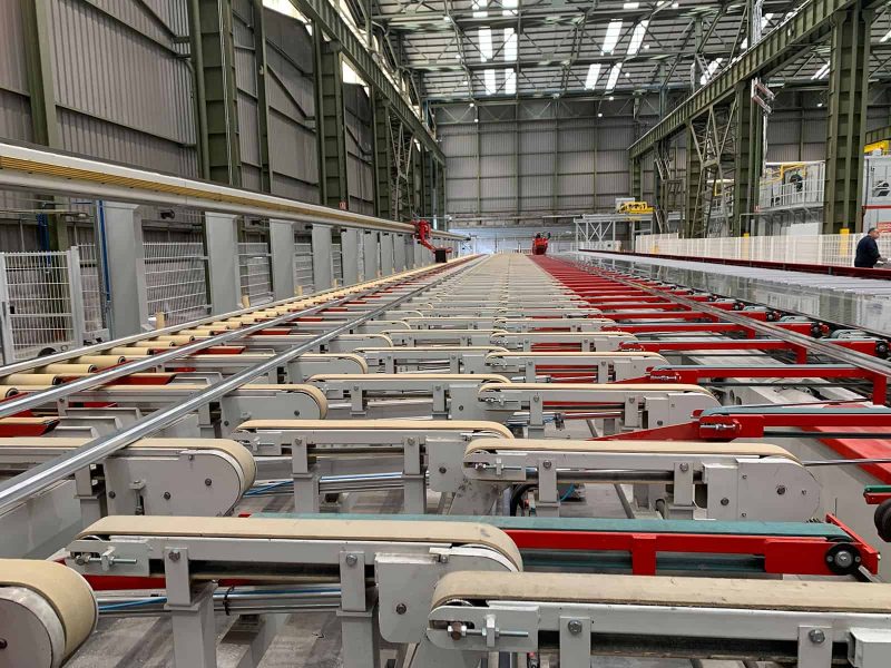
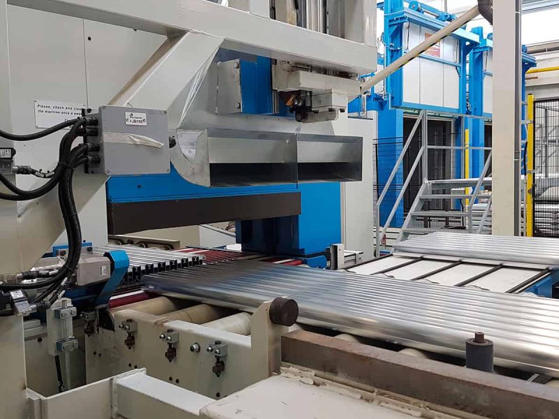
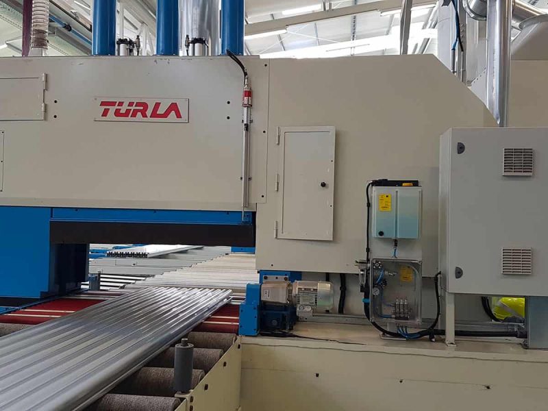
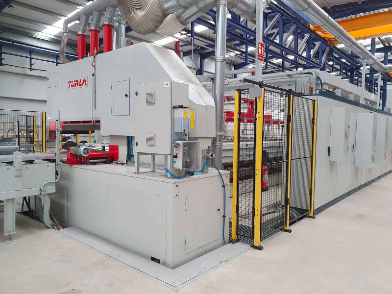
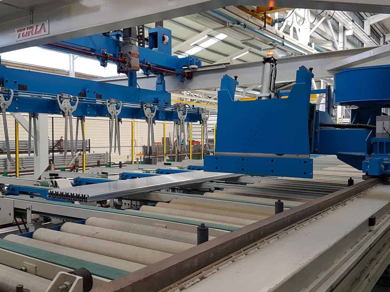
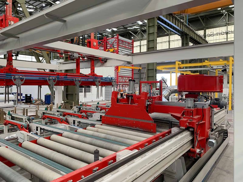
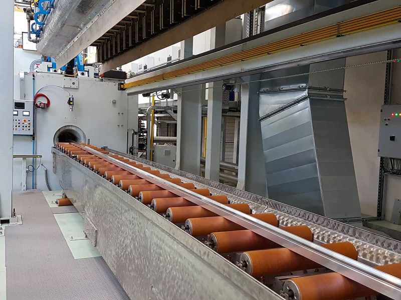
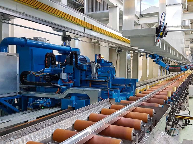
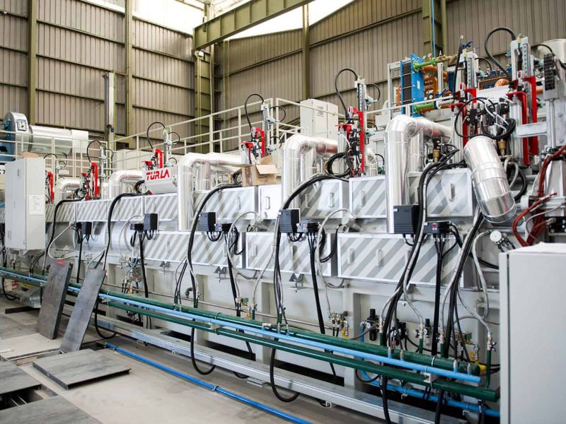
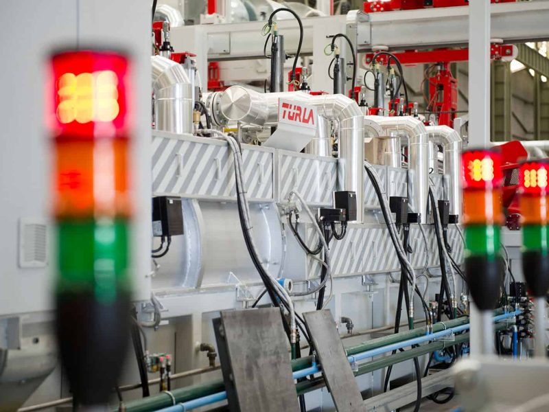
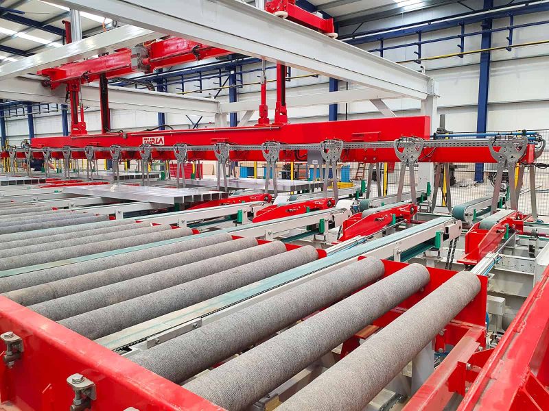
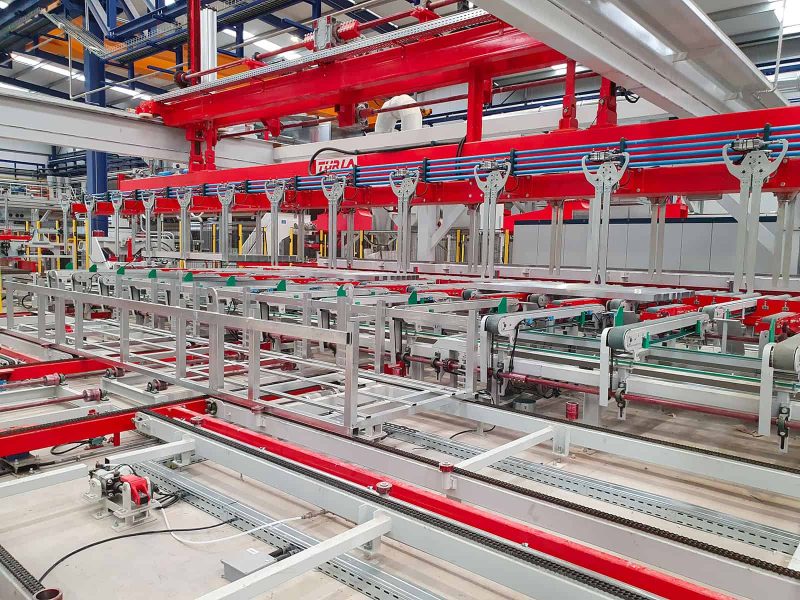
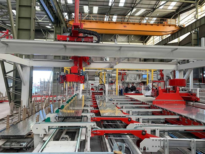
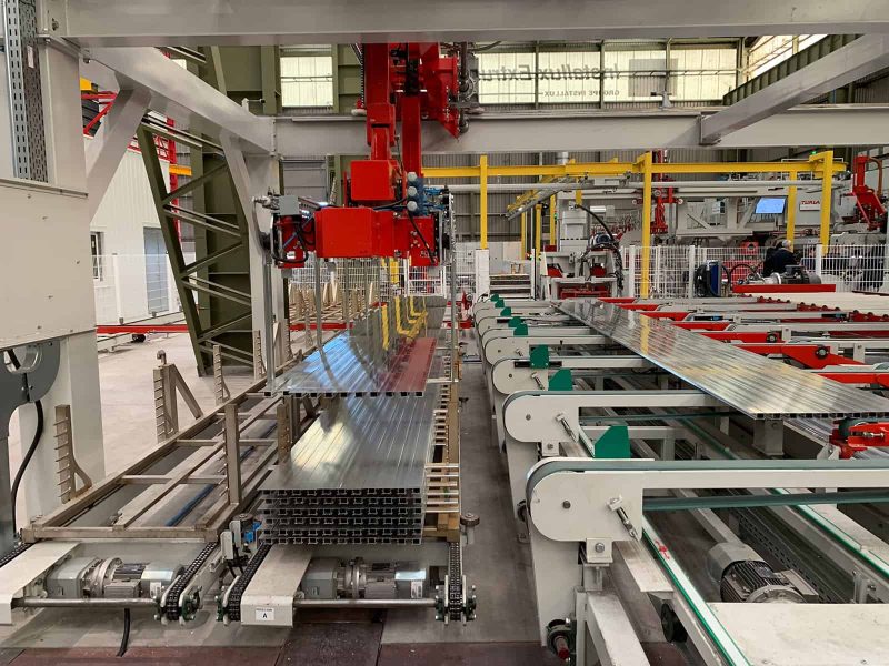
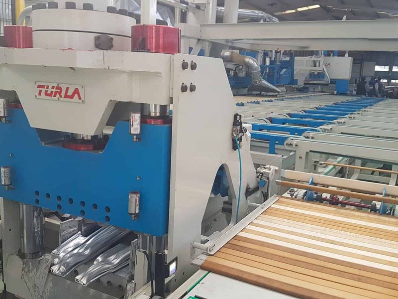
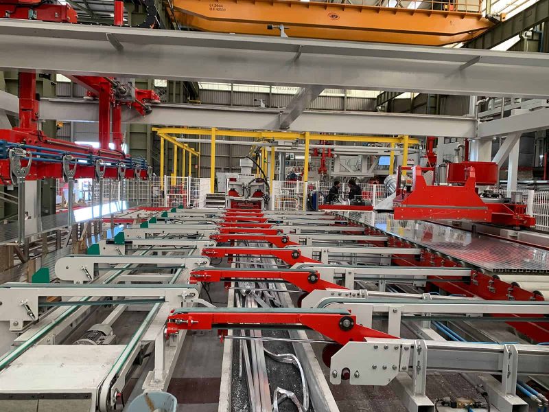
Function: To support the extrusions during the cooling phase and transport them toward the stretcher area.
Construction: These belts are engineered with the utmost precision to be sturdy but precise. These belts are the result of several decades of evolution and never derail because their carrying frame is machined. The belts are supported on a sturdy structure. Two pulleys (one driven and one idle) are mounted on the ends of the belts. The tensioning of the belts is carried out by the idle pulley. The belts are driven through a common drive shaft. Belts are designed to be easily replaceable by the maintenance crew.
Extrusion press
Extrusion press
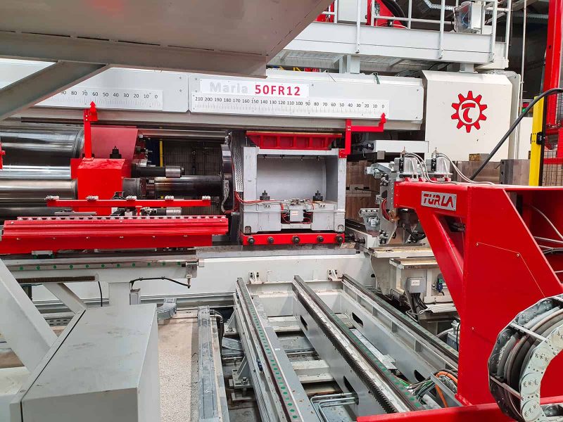
Hydraulic engineering and construction:
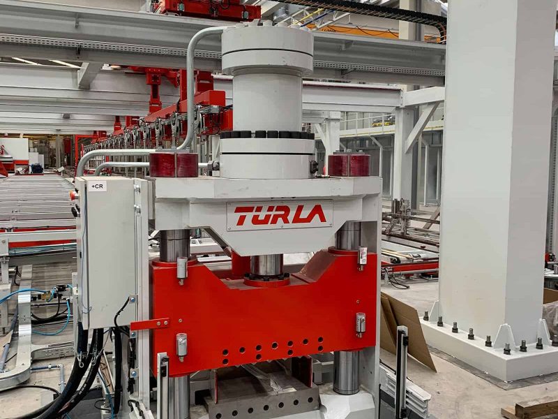
The hydraulic part has been totally engineered in cooperation with main hydraulics experts. Our presses are engineerd with the target of never exceeding 220 bar when nominal force is applied. This guarantees much less stress from the hydraulic point of view. Less stress means also less extraordinary maintenance due to less frequent unexpected break-downs.
In order to meet this target the main cylinder diameter, as well as the side cylinders, are larger than the average.
Also the amount of main and auxiliary pumps is greater in order to ensure the pumps never exceed 65% of their maximum power during normal extrusion. This dramatically minimises the stress on the pumps. It is worthwhile to mention that any movement on the press can be operated by any of the pumps so that hydraulic power can be directed wherever necessary. This provides full operating flexibility and minimises downtime in case of emergency. All main pipes were bent rather than welded in order to minimise critical joints which could require maintenance with passing of time. Pumps can be installed on the floor or on top of the press.
Mechanical enginering and construction:
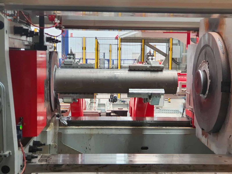
Component and assembly engineering calculations have been carried out using FEM software as well as the long experience of our specialised engineers who have been active with press engineering for more than 40 years. Forged parts are, the main platen, the back side platen, the main cylinder, the tie rods, the stem, the billet container, and other minor but critical and important parts. All forged parts undergo ultrasound tests before and after machining. The main cylinder is usually made (depending on the size of the press) of a single piece of forged steel with no welded parts. The pre-fill valve is Rexroth®. The container and side cylinders are locked in the back side of the back platen. The press frame gets pre-stressed in Turla company and the press is delivered to the customer in this status with no need to carry out this operation at customer’s site. The press configuration is front loading (billets are loaded between the die and the billet container). The press is equipped with a hydraulic die locking system to prevent any movement of the die. The front main platen of the press is totally flat and there are no pipes, no mechanical device which requires intervention, inspection, maintenance etc. Any water or air quench can be located nearest to the press face without any space or temperature loss thus maximising cooling down ramp efficiency 500-250°C. The press mouth dimensions are engineered to be as wide as possible in order to not be a limiting factor to extrusion width.
Engineering and manufacture : TF Automation, branch of Turla SRL employs SW engineers with a decades-long experience in aluminium extrusion presses, SW and automation. In order to dramatically minimise possible downtime all of the most relevant movements are equipped with double encoder and double switches in order to make sure that due to an encoder failure, mechanical damage does not occur. Another relevant feature is that each main pump motor is equipped with a dedicated soft start to minimise stress on the pumps when they are turned on at the beginning of production. In addition to this all pump motors (main pumps and auxiliaries) are provided with a double contactor to raise the safety class of the machine. All electrical cabinets are provided with air conditioning in order to make sure (independently of the final site country) the electronics devices always work at the optimal temperature. Wiring on board the press is made in such a way that in hot areas (e.g. to detect presence of billet) use of optical fibers is made to prevent break downs with conventional sensors. All sensors are “plug-in” type to allow quick replacement. Also the sensors and cables are wired in such a way to be easily accessible and of clean design to spare time during unwiring and re-wiring operations.
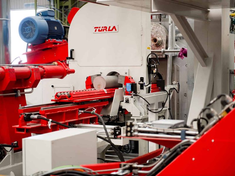
Finishing saw
Finishing saw
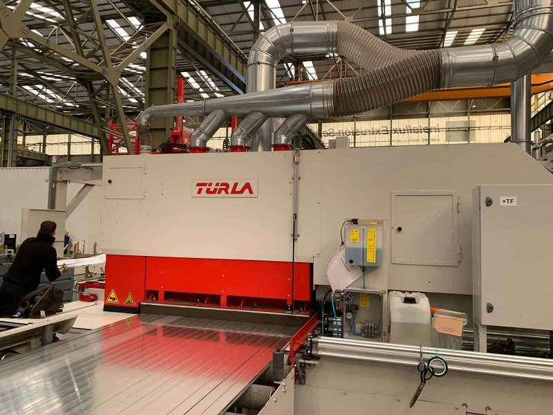
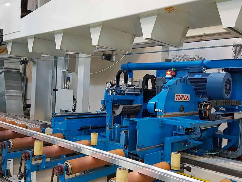
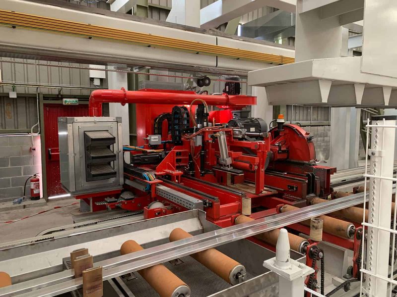
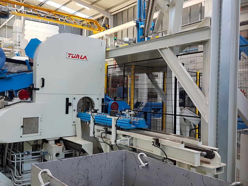
Function: To cut the profile batches to length. The length is measured by the gauge table.
Construction: This saw has been engineered in the finest detail with the utmost precision. The basic frame is constructed using a sturdy steel fabrication, which is fully stress relieved after welding.
Operation: During the cut phase the blade rises above the highest point of the profile. The blade cycle has an up-across, down and back motion. It rises up to cut (the necessary thickness only), cuts through the extrusions, lowers at the end of the stroke then returns under the extrusions. The blade cutting velocity is set by the operator directly on the panel view of the control panel. This provides a smooth and an accurately controlled cut stroke.
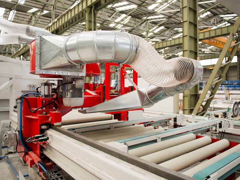
All the clamps (as well as the entire machine) are equipped with noise suppression materials to reduce the noise from the cutting operation. They also distribute the pressure over a wider area and prevent swarf from spilling out. There are four (4) chip evacuation paths. Three are located in the top hood (two in the main clamps columns and one at the side), the other is in the base section.
Gauge table
Gauge table
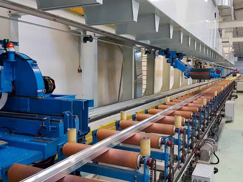
Function : Support profile batches during measuring and finishing cut.
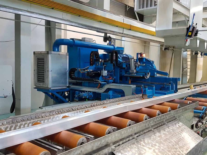
Construction: The roller table is manufactured to be strong and sturdy. Ball bearings are fitted into the ends of the rollers. The rollers are made from suitable polymeric material fitted over a metallic core. The rollers are then machined to ensure they are concentric to the beams. Driving device of rollers is engineered to be uniformly distributed over the length in such a way that there are no skid marks caused by inertia-still-turning rollers. When a table is supposed to raise and lower, its movement is very smooth in order to prevent shock-caused marks on the profiles due to sudden raising and lowering of the rollers.
Gauge stop carriage
Function: To stop the profile at the set length so as to allow the finishing cut.
Construction: The gauge head is welded, stress relieved, completely machined and finally assembled. The movement of the gauge stop carriage is controlled by the finishing saw operator who decides the length measurement of the cut. The stop carriage moves to the given position by means of electrical motor controlled through ramp devices. The stop carriage works in synchronization with the finishing saw cycle. In order to assure the carriage stays in position, specifically-engineered pneumatic devices ensure that this happens.
The gauge stop carriage runs along on high precision wheels in order to guarantee the best possible performance. As the extrusions approach the gauge stop carriage, it moves forward to ensure that all the profiles are resting against it: This cycle was invented by Turla so to make sure that all profiles touch the plate of the gauge carriage and are all at the correct length.
Hot saw
Hot saw
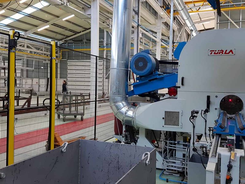
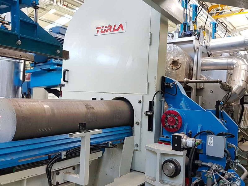
The purpose of the log saw is to cut logs down to billets according to the preset cut length. The cut length is measured through a laser beam which points toward the advancing logs. The log is firmly clamped very close to the cut point so to keep the billet steady whilst cutting. The blade is lubricated with a mist-model device so to minimize use of lubricant. A double cut cycle can be used which will allow the operator to cut the head end of the incoming log to a length that when combined with a short tail end of the exiting log the combined pieces will be the correct required billet length. A log saw gives the advantage of a flat-to-flat coupling surface when a billet is to meet the next in the press container. This prevents potential formation of air bubbles trapped between two consequential billets. The saw works with an electrical motor and its pivoting (cutting) stroke is hydraulic. The cut feed is controlled and programmable. Automatic blade wear sensors are provided.
Lead out table
Lead out table
Support the profile during the extrusion process as soon as it leaves the press. Works as a support for the hot profile saw or shear.
Construction: The very initial part of the leadout table is the initial adjustable table which, when a quench unit is supplied, is fully integrated with it. The rollers in contact with the profile are made up of a high temperature-resistant sleeve. Two ball bearings support the roller. The very conventional and stationary version of the leadout table is the model “C”. “C” means “Conventional”.
Log gas heated furnace SteP5
Log gas heated furnace SteP5
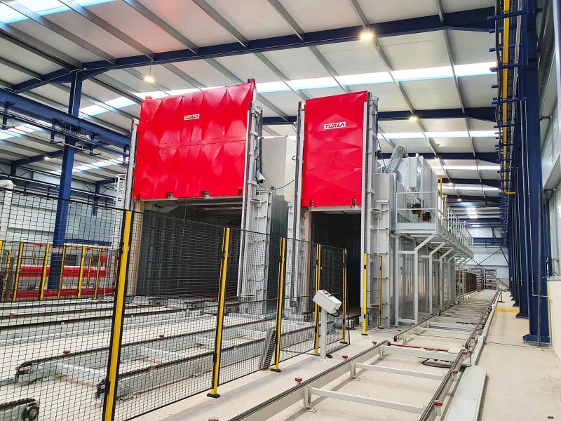
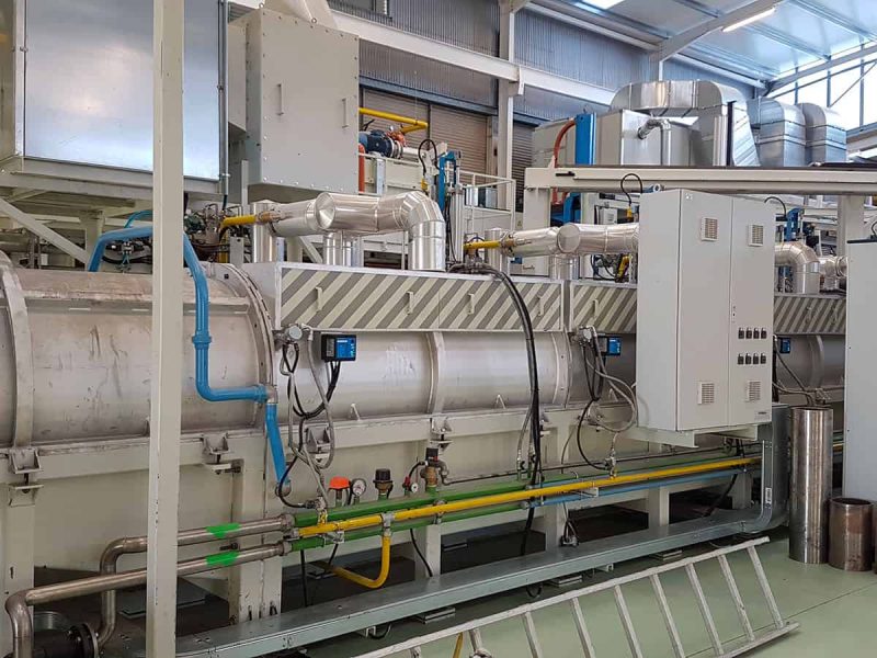
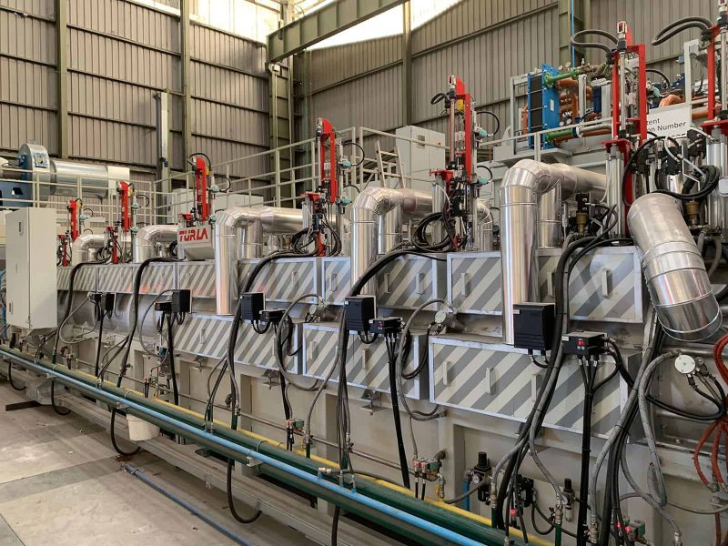
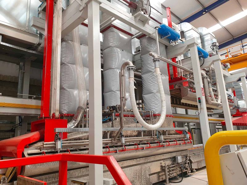
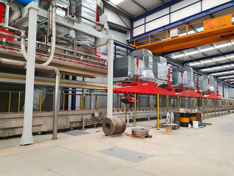
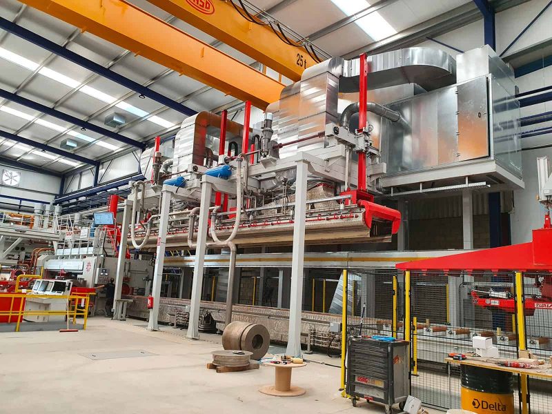
The furnace itself is of the tunnel type whereby the logs are moved along by being pushed from the back, advancing on idle rollers. The type of heating fuel is natural gas combustion with direct flame. The direct heating area is divided into self-controlled and independent zones.
STeP5 concept benefits
– Extremely Low gas consumption (the lowest on the market!)
– Reduced environmental footprint thanks to low gas consumption
– Extended rollers life time (guaranteed lifetime = 5 years)
– Possibility to run ECONOMY or PRODUCTION mode
– Operators can read present (instant) zone consumption at any time as well as total gas consumption per ton in real time!
Log heater running mode
– Energy saving MODE: the operator or press chief can decide to set an upper limit to the oven consumption. The oven will automatically run at a given rate but will never exceed the consumption limit set by the operator. A warning signal will inform the operator that the required production cannot be reach if, before that, the maximum consumption limit is reached before. The operator can also see in REAL TIME the gas consumption PER EACH ZONE of the oven and, in full environmental responsibility, he can choose to give more or less power to each zone, therefore effecting and influencing the behavior and consumption of the oven in each condition he would like this to happen.
– Full production MODE: This machine is engineered to deliver the maximum throughput the customer purchased the furnace for. The consumption, compared to other furnaces on the market remains incredibly lower but, the system, in this mode, will take care of delivering just the required amount of tons per hour.
Log hot saw
Log hot saw
The purpose of the log saw is to cut logs down to billets according to the preset cut length. The cut length is measured through a laser beam which points toward the advancing logs. The log is firmly clamped very close to the cut point so to keep the billet steady whilst cutting. The blade is lubricated with a mist-model device so to minimize use of lubricant. A double cut cycle can be used which will allow the operator to cut the head end of the incoming log to a length that when combined with a short tail end of the exiting log the combined pieces will be the correct required billet length. A log saw gives the advantage of a flat-to-flat coupling surface when a billet is to meet the next in the press container. This prevents potential formation of air bubbles trapped between two consequential billets. The saw works with an electrical motor and its pivoting (cutting) stroke is hydraulic. The cut feed is controlled and programmable. Automatic blade wear sensors are provided.
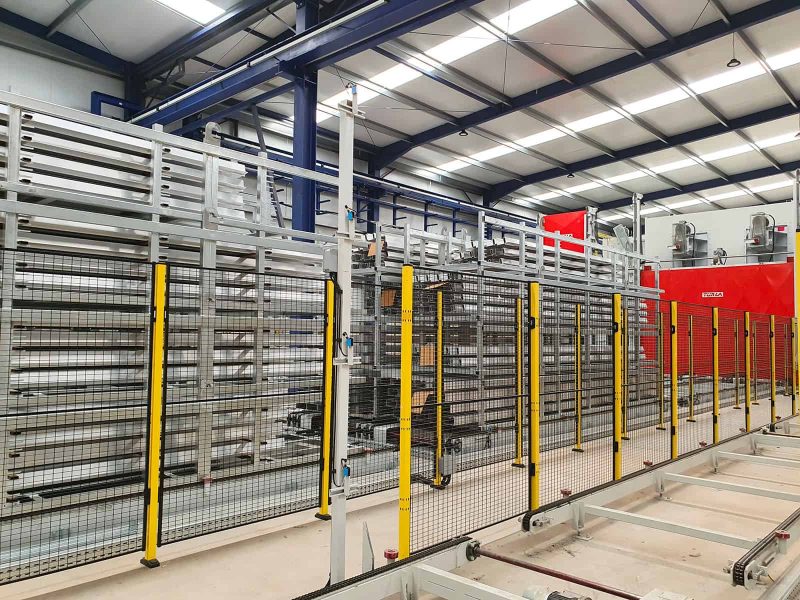
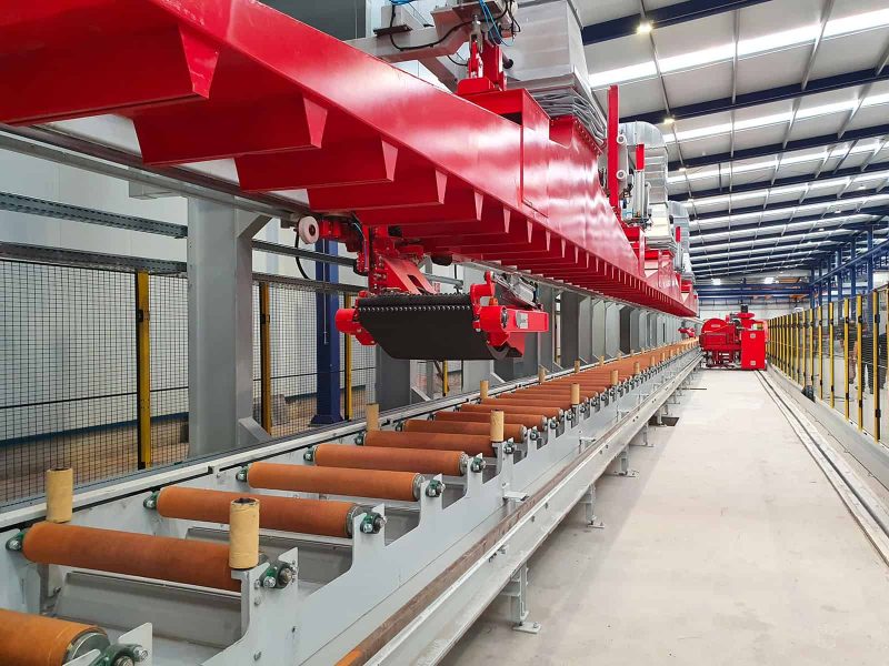
Profile stacker
Profile stacker
The machine consists of:
A) Main support structure
B) Upper Horizontal Stroke carriage
C) Vertical Stroke Gripper carriage
D) Spacer container infeed/outfeed
E) Spacer Magnet carriage
F) Spacer distribution device
A) Main support structure
The structure that supports the stacker is made of four uprights sitting on the floor. Two runways will be located on the upper part to let the (B) carriage run horizontally. The frame is engineered to be strong and robust.
B) Upper Horizontal Stroke carriage
This unit is made of a beam and two heads on which specifically-engineered wheels are mounted. The wheels are made of a self-lubricating high resistance material that prevents the wearing of the guides. The horizontal stroke of this unit is controlled by the PLC so that the utmost accuracy is guaranteed. Movement of the carriage is achieved electrically.
C) Vertical Stroke Gripper carriage
This unit is electrically driven by a motor and vertically guided to obtain accurate alignment with the basket. Each stacker undergoes (as required by our internal ISO9001 standards) a strict engineering process to ensure a reliable functional unit. Acceleration and deceleration ramps are controlled via PLC to guarantee smooth operation of the unit. The grippers assembled on this unit attach to each spacer and lift the layer of profiles.
D) Spacer container infeed/outfeed conveyor
A manual conveyor will permit the loading and the unloading of the spacer container to and from the spacer feeding position. The spacers boxes are to be loaded by means of a fork lift or a bridge crane onto a carriage to which four roller bearing wheels are attached. The carriage has to be manually located under the (E) spacers magnets carriage.
E) Spacer Magnet carriage
The funciotn of this device is to pick up a layer of steel (magnetic) sleeve covered spacers and lay them down on the spacer distribution device. The horizontal carriage wheels are made of a self-lubricating high resitance material that prevents the wearing of the guides. The vertical carriage which incorporates the magnets is located within the horizontal carriage.
F) Spacer distribution device
A carousel will be installed at the beginning of the belt to distribute the spacers brought in by the spacer magnet carriage. A toothed belt will position the spacers to the correct position under the profile pick-up position
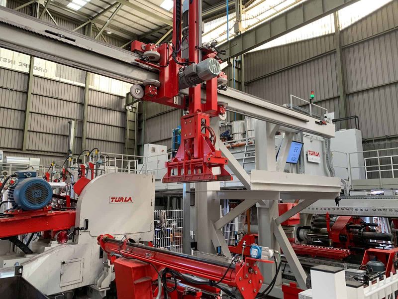
Puller
Puller
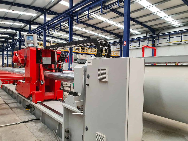
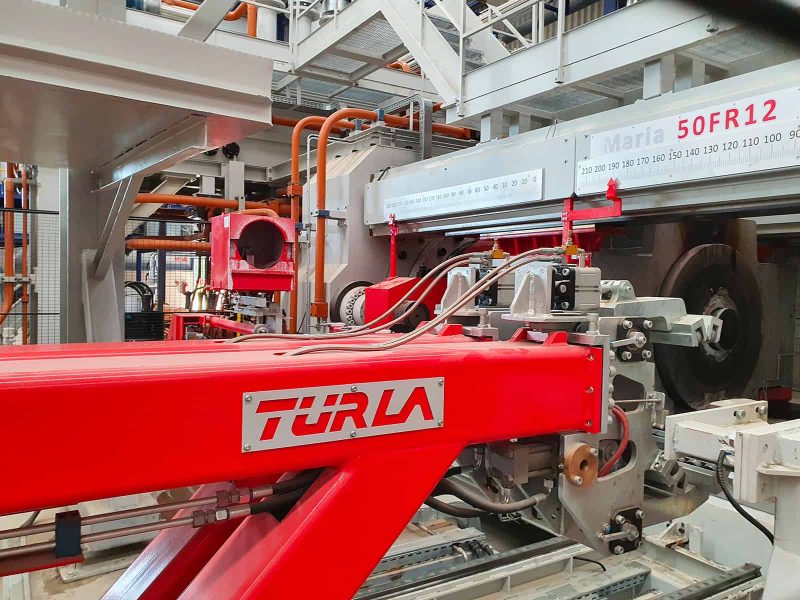
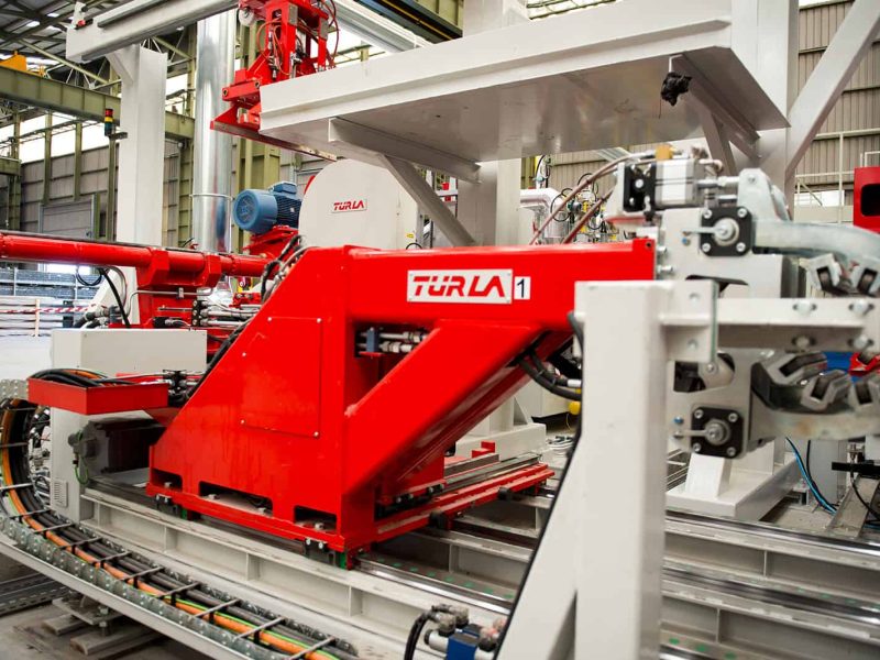
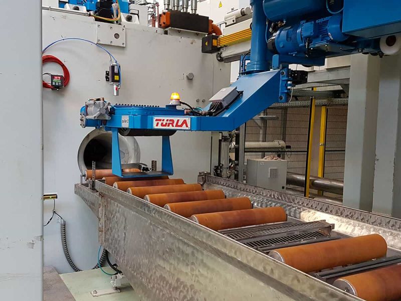
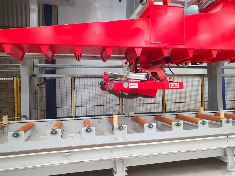
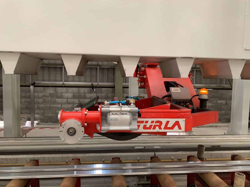
The puller guide the profiles throughout the entire extrusion length by applying a slight force and to eventually line profiles up with the stretcher headstock.
Working Principle
The puller clamp device is engineered to secure best possible hold over extrusions at all time thanks to a multi-finger “self-locking” type where fingers move independently to adapt to the profiles. The operator sets the pulling force on the main control panel. At the end of the extrusion, after the hot profiles are cut, the puller eventually positions the profile in line with the stretcher head, releases the profile and then clears away in order to get clear of the profile, then the puller returns either to the profiles cutting position or to the press because a new die has been loaded in the press and production of a new profile is to be run.
Working Cycle general description
- Puller #1 starts the extrusion.
- The press finishes extruding, stops and loads a new billet.
- Puller #1 stops when the press stops and then starts pulling again whenever the press starts extruding.
- During the dead cycle time of the press (DCT) the saw or shear cuts the profile
- As soon as saw or shear accomplished the cut, puller #1 clears away the profile and place it in line with stretcher head
- Puller #2 lowers and takes the just cut head of the profile and start pulling in synchronous with the press
- Puller #1, after having freed its jaws from profile returns to the saw or shear or to the press platen
Quench
Quench
Function: to decrease the profile temperature through direct air blow on the aluminium profile being extruded.
The Hood
When the puller has to get to the press platen, the quench hood together with its overhead air ducting is raised. When the quench hood is in the upper position a pneumatic safety lock pin will secure the hood and prevent it from falling. The shape of the air blades are equal all around the profile being extruded (upper, lower, right and left side).
The Lower part
The lower part is equipped with Kevlar® rollers. The lower part also works as the initial adjustable table.
High performance air-cooling of the profiles.
In the quench structure there are 3 upper air ducts powered by a single large air blowing station that feeds the three air nozzles located at the top, right and left of the profile. Through a PLC and frequency inverters it is possible to regulate the overall air flow from 0 to 100%, so that air delivery can be varied according to the shape, mass and symmetricity of the profile. Settings are created for each profile to optimize cooling and maximize extrusion speed. Built-in flaps will adjust the air flow from each of the three top air ducts (top, right and left). A dedicated air blowing station will provide the air inlet to the bottom part only.
Scrap system
Scrap system
Function: to cut the scrap down into pieces, by hydraulic shearing.
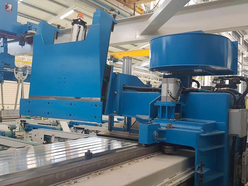
Construction: The purpose of the shear is to cut the scrapped profiles into lengths of approx. 400-500 mm and drop them onto an outfeed belt. The machine is of the guillotine type. The working principle is hydraulic. The hydraulic cylinder is located on top of the machine and has a vertical downward action to shear scrap. This machine has a robust stress relieved metallic structure which is then machined and assembled with extreme precision. The shear will be fastened to the floor.
Its hydraulic set will be mounted on the floor to allow easy inspection.
The system can be supplied with:
1) Infeed driven rubber belt: To feed the scrap shear with the scrapped profiles coming from the gauge table (length and design to be decided according to installation site dimensions etc.)
2) Outfeed driven steel belt: To evacuate the sheared profiles to an evacuation container (length and design to be decided according to installation site dimensions etc.)
Stretcher
Stretcher
Function : Stretch profiles after cooling in order to straighten them and realign tensions and molecular grain.
Construction: The machine is built from structural steel then assembled, welded, stress relieved and sand-blasted.
Stretcher Head-Stock: When the stretcher is in stretching mode, the main cylinder is in push mode. Due to the type of force this provides a lower oil pressure. On the front part of the stretcher mouth a feed-belt is usually installed, to facilitate the feeding of the profiles into the stretcher mouth.
Stretcher Tail-Stock: The frame is also heat treated (as is the head-stock) to obtain stress relief of the welds. This is to avoid deformation over time. Same as for the head-stock, all the sliding parts are machined to obtain the best possible result. The tail-stock group travels on wheels, and runs all long the entire length of the guides from the minimum stretch length to the maximum extrusion length.
Profile Locking: It is manufactured so as the clamping pressure is always proportional to the pull. In fact the upper part of the clamp is made up of a number of fingers that are independently mobile and able to adapt according to the profile’s shape. They have been engineered to lock onto the profile with a force directly proportional to the pull. Such an application increases the safety level of the machine, since only the weight of the fingers rest on the profile when the stretcher is not in pull mode.

